Descripción
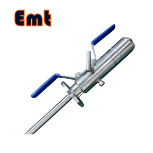
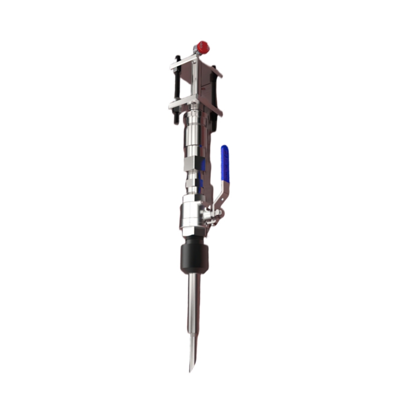
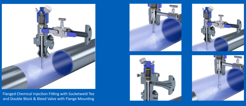
The Retractable Chemical Injection Quill is an advanced mechanism designed for precise and controlled injection of chemical inhibitors into pipelines, critical for minimizing or controlling corrosion. This device forms an integral part of the EMT Injection System, known for its reliable and safe operation under full system pressure.

1. Parameter Table
Cuerpo del accesorio de acceso
| Modelo | ||||||
| EMT-CIPA | Pluma de inyección química retráctil | |||||
| – El material del cuerpo del accesorio de acceso | ||||||
| 0 | CS | |||||
| 1 | 316SS | |||||
| 2 | 316LSS | |||||
| 3 | DÚPLEX SS | |||||
| El tipo de cuerpo de ajuste de acceso | ||||||
| B | 2″Soldado(el sufijo “clasificación de presión” se puede agregar a B) | |||||
| F | 2″ANSI Flange(suffix “pressure rating & sealing type” can be added to F) | |||||
| -Tee Size- pressure rating & sealing type if flanged end | ||||||
| 0 | Sin camiseta | |||||
| 1 | Te de 1/4″NPT(H) | |||||
| 2 | Te de 1/2″NPT(H) | |||||
| 3 | T de 3/4″NPT(H) | |||||
| 4 | Tee de 1″NPT(F) | |||||
| 5 | Orificio para brida SWN de 1/4 ″ | |||||
| 6 | Orificio para brida SWN de 1/2 ″ | |||||
| 7 | Orificio para brida SWN de 3/4 ″ | |||||
| 8 | Orificio para brida SWN de 1″ | |||||
| -Tipo/Material de cubierta protectora | ||||||
| 0 | Sin cubierta protectora | Material | ||||
| 1 | Sin agujero | CS o 0 | ||||
| 2 | Con agujero | SS o 1 | ||||
| 3 | Válvula de hemorragia | DSS o 3 | ||||
| 4 | Bleed Valve, & Pressure Gauge | |||||
| Por ejemplo:EMT-CIPA-0F600#RF-2-1/CS muestra el cuerpo del accesorio de acceso a brida ANSI 600#RF de 2″ en CS, T de 1/2″NPT(F), cubierta protectora en CS sin orificio
0F600#RF: 0F_ El cuerpo del accesorio de acceso tiene bridas en CS, 600#RF _El tamaño es 2″ANSI 600#RF, 2: El tamaño de la T es 1/2NPT(F) 1: El tipo de cubierta protectora no tiene orificio /CS: Material de cala protectora en CS |
||||||
Sampler & Injector
| Modelo | |||||||||||||||||||||||||
| Y | Sampler & Injector Retractable Chemical Injection Quill | ||||||||||||||||||||||||
| -Código | Enchufar | ||||||||||||||||||||||||
| Pxxx | Tipo | Material | Caza de focas Material | ||||||||||||||||||||||
| 0 | Sin solicitud | 0 | CS | 0 | Sin solicitud | ||||||||||||||||||||
| 1 | Hueco Cuerpo de enchufe | 1 | 316SS | 3 | DSS | 1 | Junta tórica de Viton / Embalaje primario de PTFE | ||||||||||||||||||
| 2 | Cuerpo de enchufe sólido | 2 | 316LSS | 4 | Incomparar | 2 | HNBR | ||||||||||||||||||
| - Código | Tuerca de inyección | ||||||||||||||||||||||||
| Nxx | Tamaño de conexión | Material | |||||||||||||||||||||||
| 0 | Sin solicitud | 0 | CS | ||||||||||||||||||||||
| 1 | 1/4″ | 1 | 316SS | 3 | DSS | ||||||||||||||||||||
| 2 | 1/2″ | 2 | 316LSS | 4 | Incomparar | ||||||||||||||||||||
| - Código | Sampling & Injection Tubo | ||||||||||||||||||||||||
| Sxxx-lx ″ | Tamaño de conexión | Material | Boquilla | Tamaño de línea (x ″) | |||||||||||||||||||||
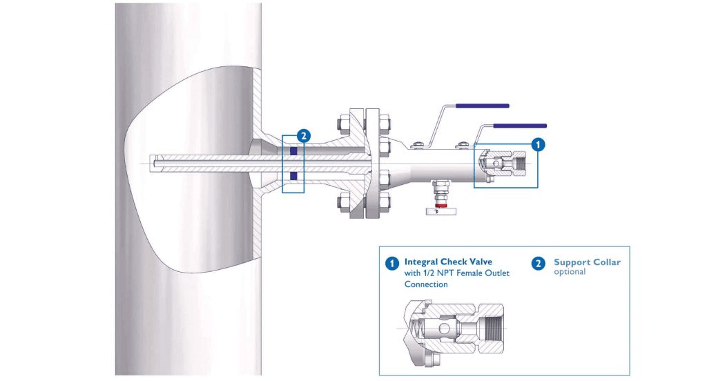
| 0 | Sin solicitud | 0 | CS | 0 | Sin solicitud | La posición más efectiva para la inyección es generalmente en el centro de la tubería. | |||||||||||||||||||
| 1 | 1/4″ | 1 | 316SS | 1 | Abierto | ||||||||||||||||||||
| 2 | 1/2″ | 2 | 316LSS | 2 | Pluma | ||||||||||||||||||||
| 3 | DSS | 3 | Cap & Core | ||||||||||||||||||||||
| 4 | Incomparar | ||||||||||||||||||||||||
| - Código | Tipo y tamaño de componentes conectados a la T y material de los componentes | ||||||||||||||||||||||||
| Txx | Tamaño de conexión | Material | |||||||||||||||||||||||
| 0 | Sin solicitud | 0 | CS | ||||||||||||||||||||||
| 1 | Boquilla de 1/4″ | a | Boquilla y válvula de 1/4″ | 1 | 316SS | ||||||||||||||||||||
| 2 | Pezón de 1/2″ | b | Boquilla y válvula de 1/2″ | 2 | 316LSS | ||||||||||||||||||||
| 3 | Pezón de 3/4″ | do | Boquilla y válvula de 3/4″ | 3 | D SS | ||||||||||||||||||||
| 4 | Pezón de 1″ | d | Boquilla y válvula de 1″ | 4 | Incomparar | ||||||||||||||||||||
| 5 | Brida de ruido de 1/4 ″* | mi | Boquilla y brida de 1/4″ | ||||||||||||||||||||||
| 6 | Brida de ruido de 1/2 ″ | F | Boquilla y brida de 1/2″ | ||||||||||||||||||||||
| 7 | Brida de ruido de 3/4 ″ | gramo | Boquilla y brida de 3/4″ | ||||||||||||||||||||||
| 8 | Brida de ruido de 1 ″ | H | Boquilla y brida de 1″ | ||||||||||||||||||||||
| For Example:SI-P221-N12-S122-L4″-T22 SI:Sampling & Injection Assembly,P221: Solid Plug Body in 316LSS Viton O-Ring and PTFE Primary Packing,N12:Injection Nut Connection Size is 1/4″and El material es 316LSS, S122: Inyección Tubo El tamaño de la conexión es 1/4″ y El material es 316LSS. El tipo de boquilla es pluma, L4 ″: para tubería de 4 ″. T22: Tamaño de conexión de pezón conectado a T es 1/2 ″ NPT (M), El material del pezón es 316LSS | |||||||||||||||||||||||||
Nota: La brida SWN es una brida WN especial
Example for a set of Sampler & Injector Assembly:
EMT-CIPA-0F600#RF-2-1+ SI-P221-N12-S122-L4″-T22
2. Key Features of the Retractable Chemical Injection Quill:
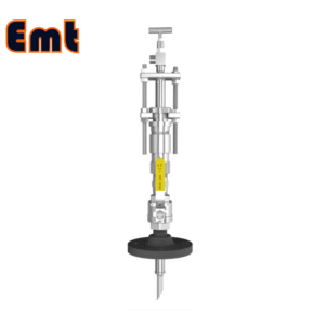
Versatile Design:
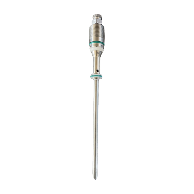
The quill is equipped with a variety of nozzle options to cater to different injection requirements, ensuring efficient delivery of chemical inhibitors directly into the pipeline system. This design allows for the adaptation to varying flow rates and viscosities of the injected chemical .
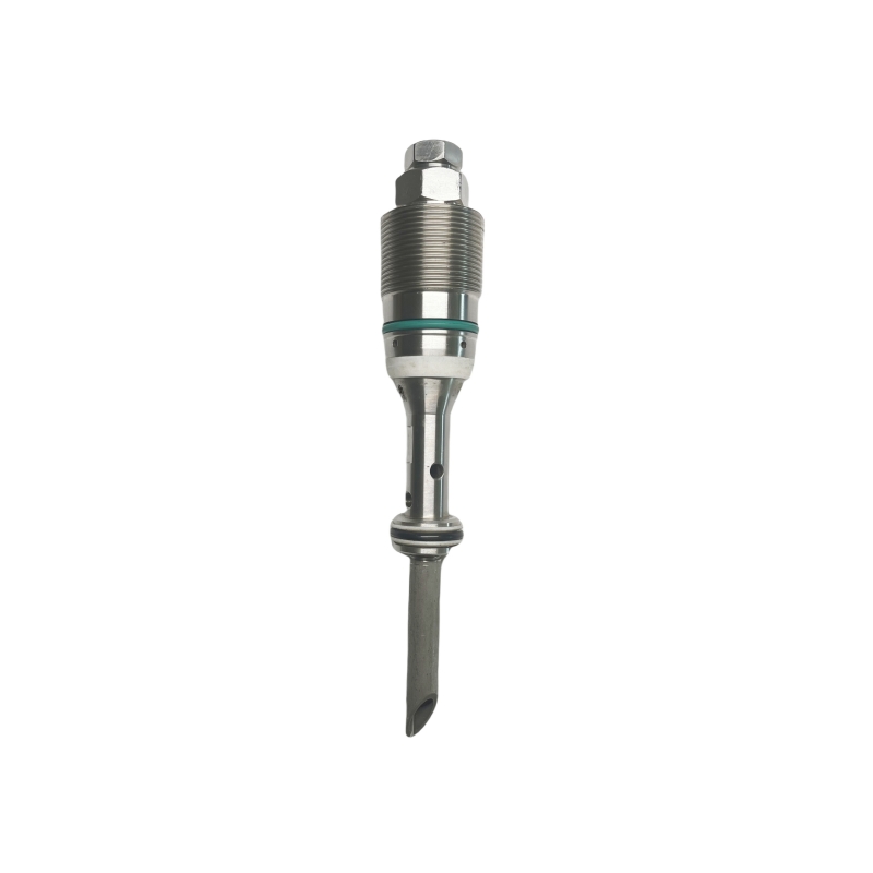
Robust Internal Assembly:
The internal components of the quill include a solid plug body, an injection nut, and an injection tube, all engineered to ensure durability and reliability. These components are connected to a Tee assembly that includes an NPT nipple, a valve, and an SWN flange to secure and stabilize the installation.
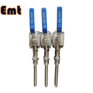
Flexible Process Connections:
The quill supports multiple connection sizes, including a 2″ flange, 2″ Flareweld access fitting, and 1″ Nipple to NPT ball valve, offering flexibility to match specific pipeline configurations and requirements.
High Operational Standards:
Designed to operate effectively within a temperature range of -20 ℃ to 150 ℃ and withstand pressures up to 6000 PSI, the quill is suitable for harsh environments and high-pressure applications typical in industrial settings.
3. Customization Options:
The EMT Injection System offers extensive customization through its varied Access Fitting Body options, such as:
- Material Options. Available in Carbon Steel (CS), 316 Stainless Steel (316SS), 316L Stainless Steel (316LSS), and DUPLEX Stainless Steel (DUPLEX SS).
- Connection Types. Options include a 2″ Welded configuration or a 2″ ANSI Flange, with additional specifications for pressure ratings and sealing types.
- Tee Sizes. Various Tee sizes are available ranging from 1/4″ NPT to 1″ NPT, as well as options for SWN Flange connections.
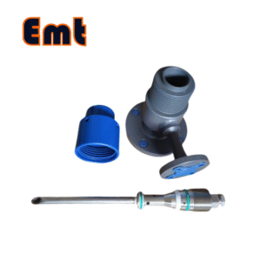
- Protective Cover Types. Choices range from no protective cover to covers equipped with or without holes, with bleed valves, and options for integrating pressure gauges.
4. Example Configuration:
For instance, an EMT-CIPA model with the specification 0F600#RF-2-1/CS includes a 2″ ANSI 600#RF Flange Access Fitting Body in Carbon Steel, a 1/2″ NPT(F) Tee, and a protective cover in Carbon Steel without holes. This demonstrates the modularity and adaptability of the system to meet specific operational needs and environmental conditions.