Description
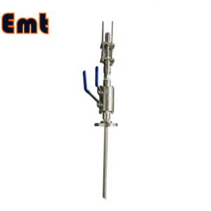
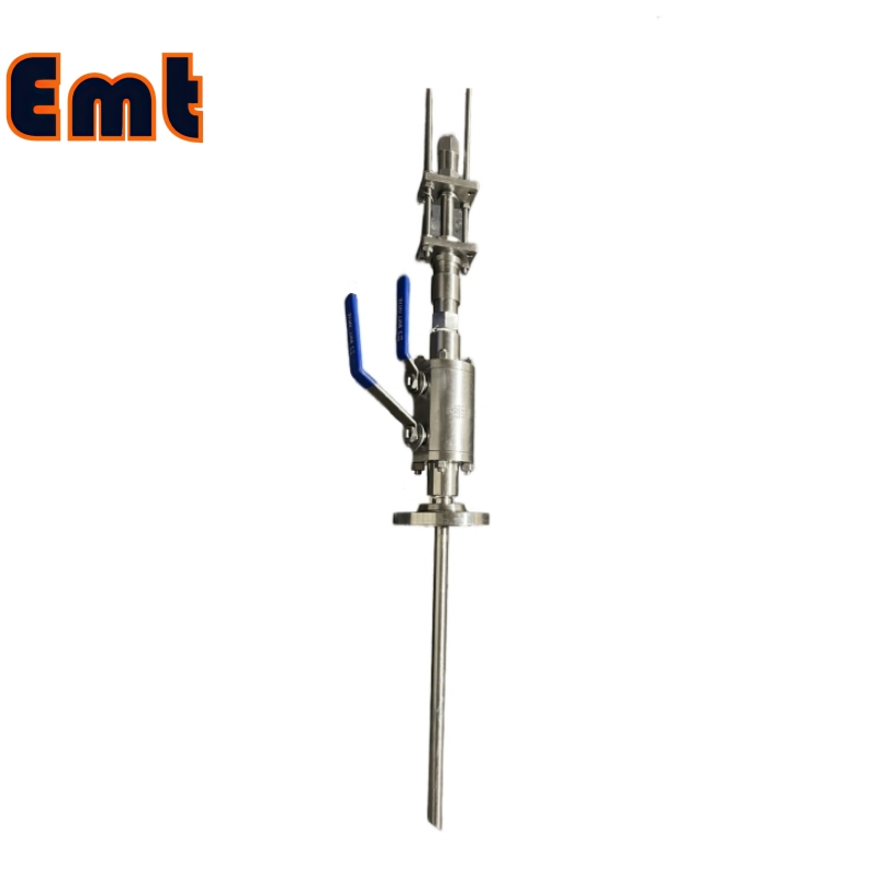
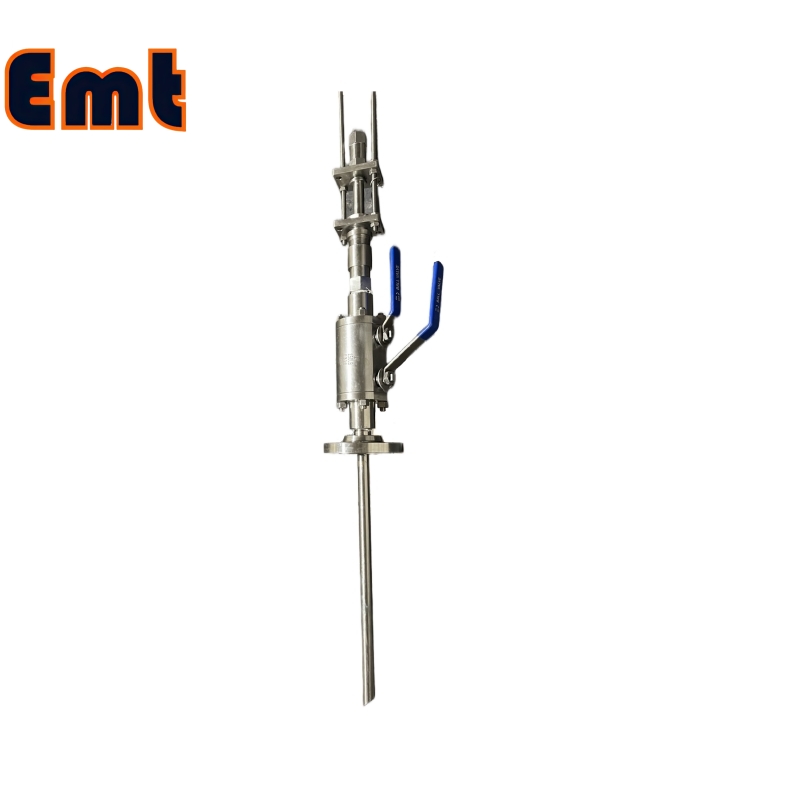
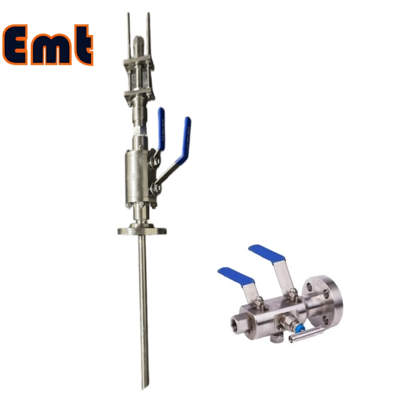
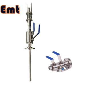
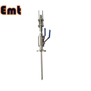
A chemical injection quill with a Double Block and Bleed (DBB) valve is a crucial component in many industrial processes, particularly in the oil, gas, and petrochemical sectors. This assembly is specifically designed to inject chemicals into a pipeline or vessel while ensuring precise control and safety.
In essence, the functionality of a chemical injection quill is fundamental to maintaining the integrity and efficiency of industrial systems where chemical treatments are necessary. Its capability to deliver chemicals precisely and safely underpins its critical role in modern industrial operations.
Functionality of Chemical Injection Quill
The chemical injection quill, designed for precision and durability, plays a crucial role in harsh industrial environments. It ensures that chemicals are introduced at the optimal point in a pipeline or vessel. This placement achieves uniform distribution throughout the system. This is particularly important in processes where chemical reactions are sensitive to concentration and mixing levels, such as in water treatment, corrosion inhibition, or scale prevention.
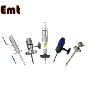
The design of the quill often includes features that enhance its effectiveness and longevity. For example, the tip of the quill can be customized with different nozzle designs. These designs control the flow rate and dispersion pattern of the injected chemicals. This customization allows for precise control over chemical introduction. It ensures chemicals are evenly distributed, even under varying flow conditions.
Moreover, chemical injection quills are engineered to withstand the corrosive or abrasive nature of the chemicals they handle. The choice of material, such as high-grade stainless steel, Hastelloy, or titanium, depends on the specific chemicals and operating conditions. These materials are selected for their ability to resist corrosion, erosion, and other forms of degradation, thereby extending the service life of the quill and reducing maintenance needs.
Additionally, the installation of a chemical injection quill is designed for seamless integration. Connections are typically made via threaded, welded, or flanged joints. These ensure a secure and leak-proof integration into the pipeline system. This secure installation prevents any bypass of chemicals around the injection point. It maximizes the effectiveness of the treatment and prevents damage to pipeline components.
Role of the DBB Valve
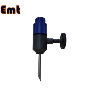
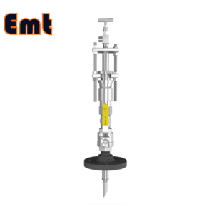
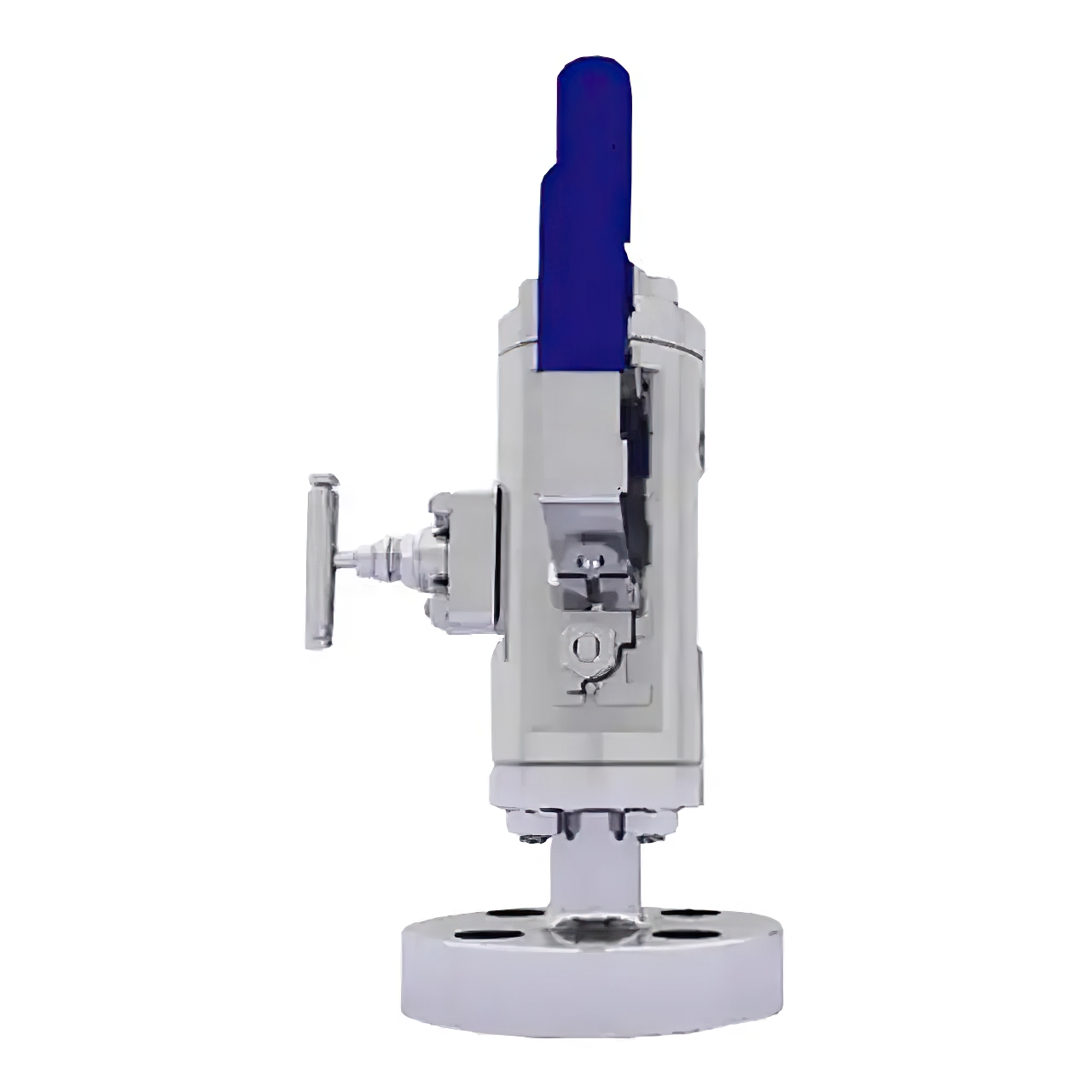
Incorporating a DBB valve adds a critical safety and maintenance feature. The DBB valve consists of two separate block valves and a bleed valve in a single assembly. This configuration allows for the isolation of the chemical injection point from the rest of the system. Operators can close the two block valves to securely isolate the quill, and the bleed valve can then be opened to relieve any pressure and clear the line of chemicals before maintenance or inspection.
Advantages
The DBB valve significantly enhances safety in the operation of chemical injection systems. It provides reliable isolation and allows operators to depressurize the quill safely. This feature is crucial in preventing accidents and ensuring the well-being of personnel and the preservation of equipment.
Efficiency is another key benefit. Direct injection of chemicals into the fluid stream ensures optimal mixing and reaction with the process fluids. This method enhances the effectiveness of the chemical treatment, making the process more efficient and yielding better results.
The inclusion of the DBB valve also simplifies maintenance and inspection activities. Operators do not need to shut down the entire system to service the chemical injection quill. This ease of maintenance not only saves time but also reduces the risk of system downtime, which can be costly.
Additionally, operators have the ability to precisely control injection rates, adjusting them based on the specific needs of the process or the properties of the fluids being treated. This precise control helps protect equipment and personnel while enhancing the overall efficiency and effectiveness of the process. The consistent and safe application of chemical treatments ensures that the system operates at peak efficiency, reducing waste and improving output quality.

Selection Model Form of the Chemical Injection Quill
| Model | ||||||||||||||||||||||||||||
| SI | Chemical Injector Quill | |||||||||||||||||||||||||||
| -Code | Plug | |||||||||||||||||||||||||||
| Pxxx | Type | Material | Sealing Material | |||||||||||||||||||||||||
| 0 | No Request | 0 | CS | 0 | No Request | |||||||||||||||||||||||
| 1 | Hollow Plug Body | 1 | 316SS | 3 | DSS | 1 | Viton O-Ring / PTFE Primary Packing | |||||||||||||||||||||
| 2 | Solid Plug Body | 2 | 316LSS | 4 | INCONEL | 2 | HNBR | |||||||||||||||||||||
| – Code | Injection Nut | |||||||||||||||||||||||||||
| Nxx | Connection Size | Material | ||||||||||||||||||||||||||
| 0 | i.e. No Request | 0 | i.e. CS | |||||||||||||||||||||||||
| 1 | i.e. 1/4″ | 1 | i.e. 316SS | 3 | i.e. DSS | |||||||||||||||||||||||
| 2 | i.e. 1/2″ | 2 | i.e. 316LSS | 4 | i.e. INCONEL | |||||||||||||||||||||||
| – Code | Injection Tube | |||||||||||||||||||||||||||
| Connection Size | Material | Nozzle | Line size(x″) | |||||||||||||||||||||||||
| Sxxx-Lx″ | ||||||||||||||||||||||||||||
| 0 | No Request | 0 | CS | 0 | i.e. No Request | The most effective position for injection is generally at the center of the pipe | ||||||||||||||||||||||
| 1 | i.e. 1/4″ | 1 | i.e. 316SS | 1 | i.e. Open | |||||||||||||||||||||||
| 2 | i.e. 1/2″ | 2 | i.e. 316LSS | 2 | i.e. Quill | |||||||||||||||||||||||
| 3 | i.e. DSS | 3 | i.e. Cap & Core | |||||||||||||||||||||||||
| 4 | i.e. INCONEL | |||||||||||||||||||||||||||
| – Code | Nipple and Valve(or end Flange)of Tee | |||||||||||||||||||||||||||
| Txx | Connection Size | Material | ||||||||||||||||||||||||||
| 0 | i.e. No Request | 0 | i.e. CS | |||||||||||||||||||||||||
| 1 | i.e. 1/4″Nipple | a | i.e. 1/4″Nipple and Valve | 1 | i.e. 316SS | |||||||||||||||||||||||
| 2 | i.e. 1/2″Nipple | b | i.e. 1/2″Nipple and Valve | 2 | i.e. 316LSS | |||||||||||||||||||||||
| 3 | i.e. 3/4″Nipple | c | i.e. 3/4″Nipple and Valve | 3 | i.e. D SS | |||||||||||||||||||||||
| 4 | i.e. 1″Nipple | d | i.e. 1″Nipple and Valve | 4 | i.e. INCONEL | |||||||||||||||||||||||
| 5 | i.e. 1/4″Flange | e | i.e. 1/4″Nipple end Flange | |||||||||||||||||||||||||
| 6 | i.e. 1/2″Flange | f | i.e. 1/2″Nipple end Flange | |||||||||||||||||||||||||
| 7 | i.e. 3/4″Flange | g | i.e. 3/4″Nipple end Flange | |||||||||||||||||||||||||
| 8 | i.e. 1″Flange | h | i.e. 1″Nipple end Flange | |||||||||||||||||||||||||
| For Example, SI-P221-N12-S122-L4″-T22 | ||||||||||||||||||||||||||||
| SI:e.g. Sampling & Injection Assembly, | ||||||||||||||||||||||||||||
| P221: e.g. Solid Plug Body in 316LSS Viton O-Ring and PTFE Primary Packing, | ||||||||||||||||||||||||||||
| N12:e.g. injection Nut Connection Size is 1/4″and Material is 316LSS, | ||||||||||||||||||||||||||||
| S122:e.g. injection Tube Connection Size is 1/4″ and Material is 316LSS. Type of nozzle is quills | ||||||||||||||||||||||||||||
| L4″:For 4″pipe. | ||||||||||||||||||||||||||||
| T22: Nipple of Tee Connection Size is 1/2″, Nipple material is 316LSS | ||||||||||||||||||||||||||||