Description
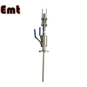
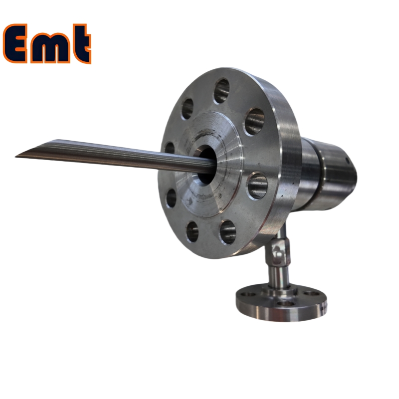
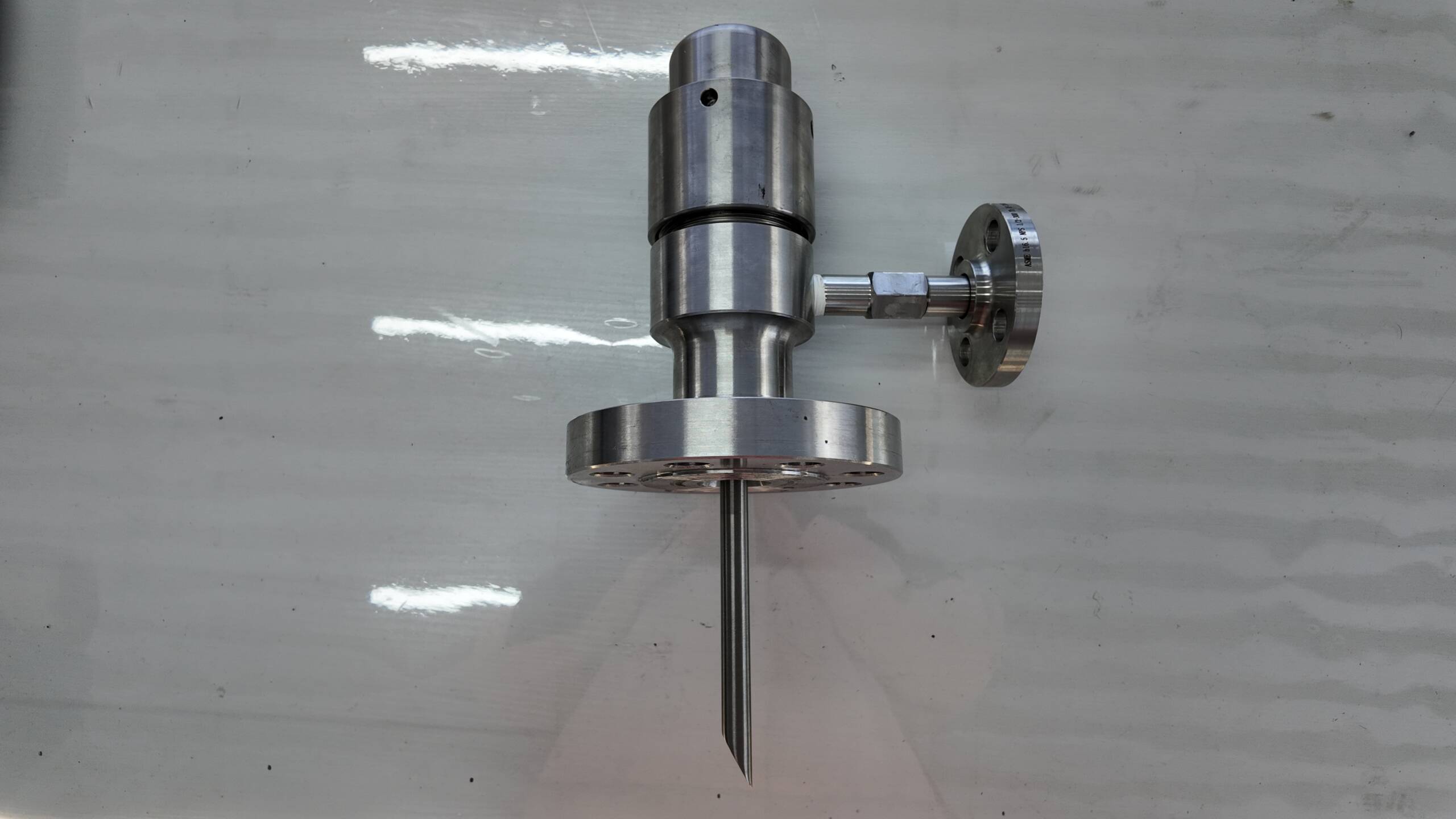
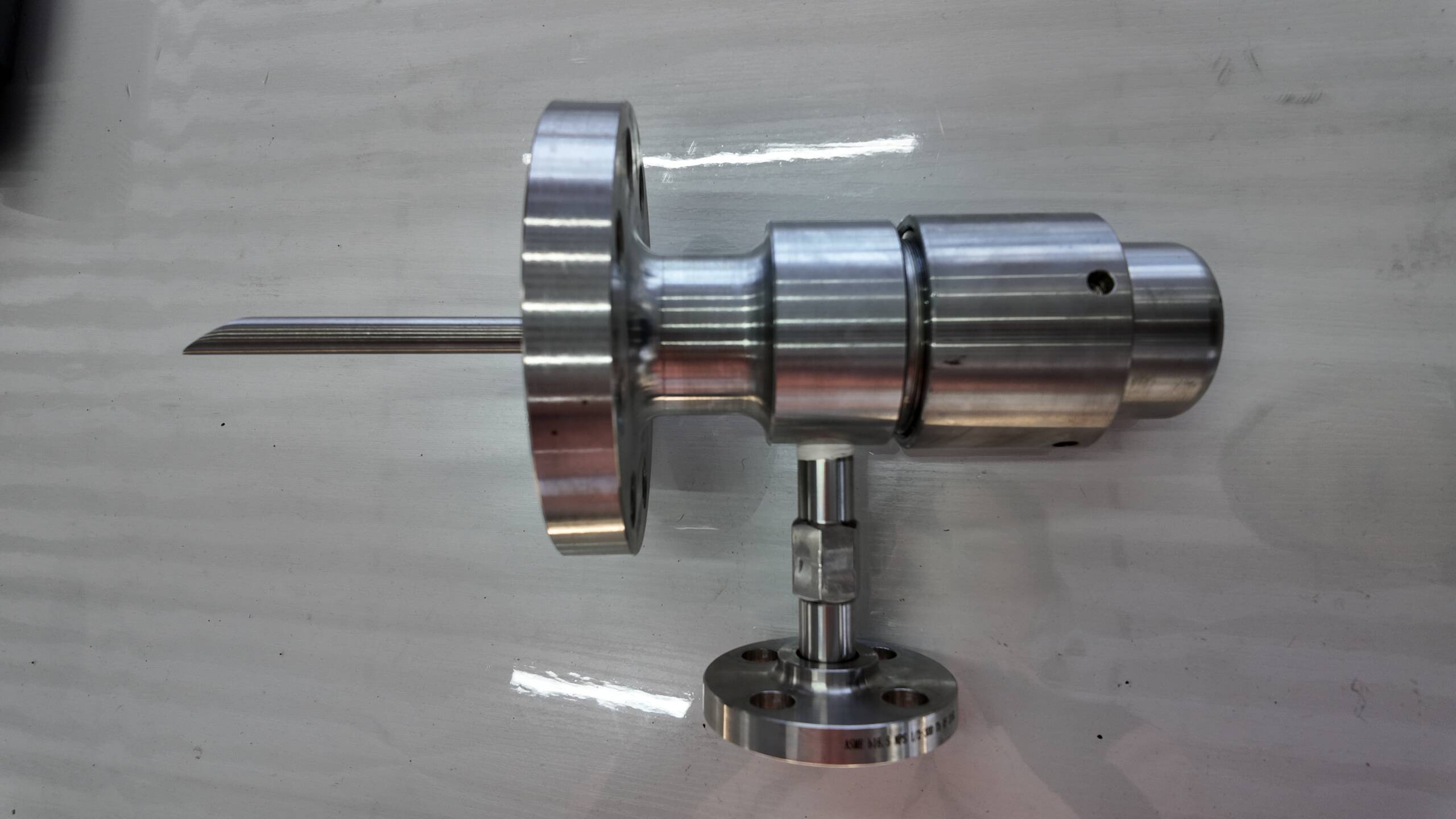
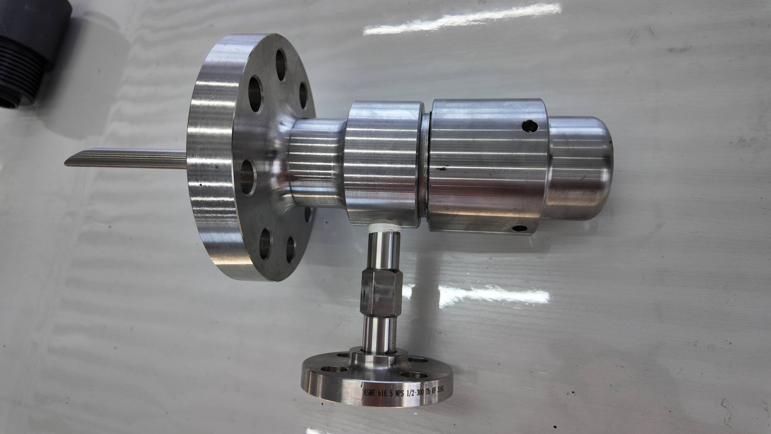
EMT Flange Connection Chemical Injection Quill
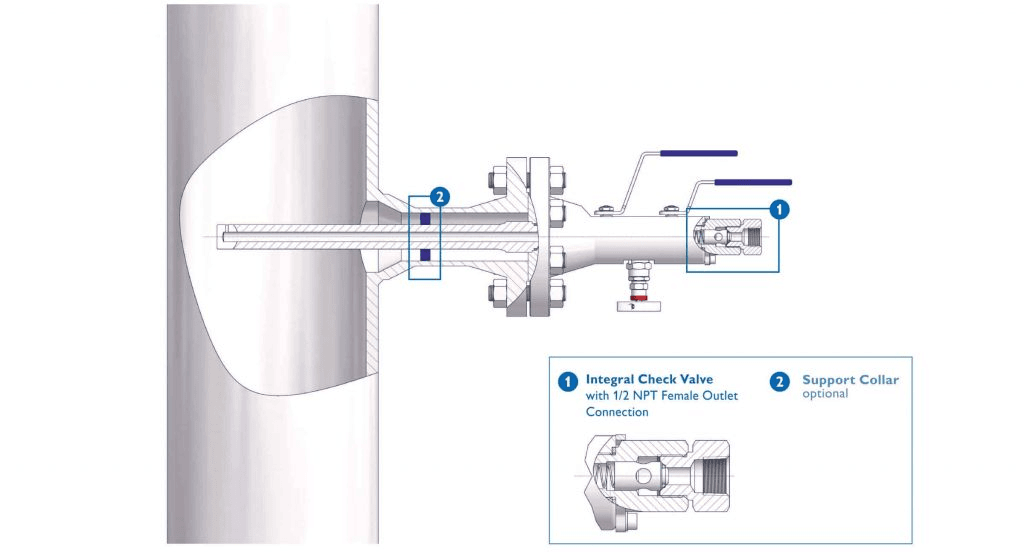
The EMT Flanged Injection Quill is an indispensable tool in industries such as oil and gas, water treatment, and chemical processing. This device ensures the safe and precise delivery of chemicals into pipelines or process systems. It features a flanged connection that securely attaches to pipelines, preventing leaks in high-pressure environments. The construction of the quill from stainless steel offers resistance against corrosive chemicals and extreme temperatures, enhancing its durability. It also allows for accurate chemical dosing, minimizing waste and ensuring optimal integration at the center of the pipeline. Furthermore, the quill’s design includes mechanisms that prevent backflow, safeguarding the chemical feed system from external exposure.
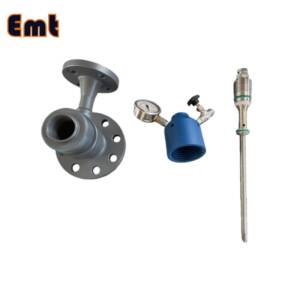
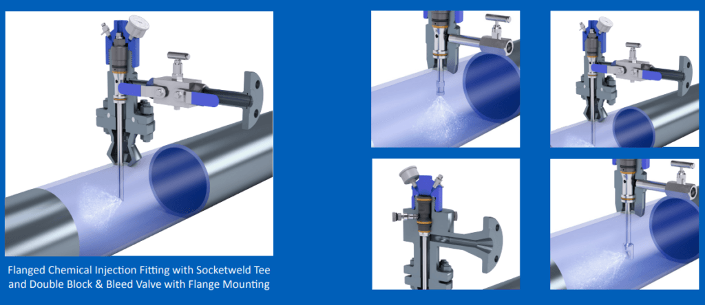
Transitioning to its functionality, the EMT Flanged Injection Quill excels in promoting rapid and uniform chemical mixing within the flow stream. This capability is essential for maintaining process efficiency and effectiveness. It includes a check valve that enhances safety by preventing the reverse flow of chemicals. This feature is critical in maintaining the integrity of the chemical injection system. The quill’s versatility makes it suitable for a variety of industrial applications, adapting easily to different pressures and chemical properties. Its robust design and functional excellence make it a reliable choice for managing chemical injections in complex industrial settings.
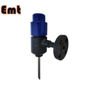
Flange Connection
Flange connections offer notable advantages in assembly and maintenance of piping systems. They provide a strong, leak-proof seal ideal for high-pressure applications. Additionally, flanges allow for quick disassembly and reassembly, facilitating easy access during repairs or inspections. This feature drastically reduces downtime in industrial operations. Moreover, flange connections ensure precise alignment of piping, enhancing overall system stability. They also accommodate various materials and sizes, promoting versatility across numerous applications. Thus, these connections are indispensable in settings requiring robust, reliable piping solutions.
Parameters of EMT Chemical Injection Quill
| Category | Details |
| Product Information | |
| Product Name | Chemical Injection Quill |
| Brand Name | EMT Pigging |
| Condition | New |
| Type | Injection & Sampling System |
| Certification | ISO 9001 |
| Warranty | 1.5 years |
| Place of Origin | Liaoning, China |
| Physical Specifications | |
| Weight (KG) | 5 |
| Package Size (cm) | 35 x 40 x 60 |
| Gross Weight (Package, kg) | 8 |
| Material and Construction | |
| Sealing Material | Fluororubber |
| Solid Plug Assembly | 316L Stainless Steel |
| Injection Tube | 316L Stainless Steel |
| NPT Nozzle | 316L Stainless Steel |
| Flange Material | ASTM A105N |
| Operational Parameters | |
| Working Temperature (°C) | -20 to 200 |
| Operation Temperature (°C) | -20 to 150 |
| Working Pressure (LB) | 150LB, 300LB, 600LB, 900LB, 1500LB |
| Pressure Rating (PSI) | 6000 PSI or as per Flange Size |
Applications
The EMT Flanged Injection Quill plays a pivotal role across various sectors. In corrosion control, it injects inhibitors directly into pipelines, preventing internal damage. For water treatment applications, it adds precise doses of disinfectants or coagulants, ensuring water safety and clarity. Additionally, this quill enhances chemical processing by delivering exact chemical amounts, optimizing reaction outcomes. It also combats mineral scale buildup in boilers and cooling towers by injecting scale inhibitors efficiently.
Moreover, the injection quill proves essential in maintaining pipeline integrity in the oil and gas industry through precise inhibitor and biocide dosing. In chemical processing sectors, it ensures consistent and controlled reactions by providing exact reactant volumes. Overall, the EMT Flanged Injection Quill is crucial where accurate chemical dosing is key to system efficiency and safety, making it a valuable asset in industrial processes.
Selection Model
| Model | |||||||||||||||||||||||||||
| SI | Chemical Injector Quill | ||||||||||||||||||||||||||
| -Code | Plug | ||||||||||||||||||||||||||
| Pxxx | Type | Material | Sealing Material | ||||||||||||||||||||||||
| 0 | No Request | 0 | CS | 0 | No Request | ||||||||||||||||||||||
| 1 | Hollow Plug Body | 1 | 316SS | 3 | DSS | 1 | Viton O-Ring / PTFE Primary Packing | ||||||||||||||||||||
| 2 | Solid Plug Body | 2 | 316LSS | 4 | INCONEL | 2 | HNBR | ||||||||||||||||||||
| – Code | Injection Nut | ||||||||||||||||||||||||||
| Nxx | Connection Size | Material | |||||||||||||||||||||||||
| 0 | i.e. No Request | 0 | i.e. CS | ||||||||||||||||||||||||
| 1 | i.e. 1/4″ | 1 | i.e. 316SS | 3 | i.e. DSS | ||||||||||||||||||||||
| 2 | i.e. 1/2″ | 2 | i.e. 316LSS | 4 | i.e. INCONEL | ||||||||||||||||||||||
| – Code | Injection Tube | ||||||||||||||||||||||||||
| Sxxx-Lx″ | Connection Size | Material | Nozzle | Line size(x″) | |||||||||||||||||||||||
| 0 | No Request | 0 | CS | 0 | i.e. No Request | The most effective position for injection is generally at the center of the pipe | |||||||||||||||||||||
| 1 | i.e. 1/4″ | 1 | i.e. 316SS | 1 | i.e. Open | ||||||||||||||||||||||
| 2 | i.e. 1/2″ | 2 | i.e. 316LSS | 2 | i.e. Quill | ||||||||||||||||||||||
| 3 | i.e. DSS | 3 | i.e. Cap & Core | ||||||||||||||||||||||||
| 4 | i.e. INCONEL | ||||||||||||||||||||||||||
| – Code | Nipple and Valve(or end Flange)of Tee | ||||||||||||||||||||||||||
| Txx | Connection Size | Material | |||||||||||||||||||||||||
| 0 | i.e. No Request | 0 | i.e. CS | ||||||||||||||||||||||||
| 1 | i.e. 1/4″Nipple | a | i.e. 1/4″Nipple and Valve | 1 | i.e. 316SS | ||||||||||||||||||||||
| 2 | i.e. 1/2″Nipple | b | i.e. 1/2″Nipple and Valve | 2 | i.e. 316LSS | ||||||||||||||||||||||
| 3 | i.e. 3/4″Nipple | c | i.e. 3/4″Nipple and Valve | 3 | i.e. D SS | ||||||||||||||||||||||
| 4 | i.e. 1″Nipple | d | i.e. 1″Nipple and Valve | 4 | i.e. INCONEL | ||||||||||||||||||||||
| 5 | i.e. 1/4″Flange | e | i.e. 1/4″Nipple end Flange | ||||||||||||||||||||||||
| 6 | i.e. 1/2″Flange | f | i.e. 1/2″Nipple end Flange | ||||||||||||||||||||||||
| 7 | i.e. 3/4″Flange | g | i.e. 3/4″Nipple end Flange | ||||||||||||||||||||||||
| 8 | i.e. 1″Flange | h | i.e. 1″Nipple end Flange | ||||||||||||||||||||||||
| For Example, SI-P221-N12-S122-L4″-T22 | |||||||||||||||||||||||||||
| SI:e.g. Sampling & Injection Assembly, | |||||||||||||||||||||||||||
| P221: e.g. Solid Plug Body in 316LSS Viton O-Ring and PTFE Primary Packing, | |||||||||||||||||||||||||||
| N12:e.g. injection Nut Connection Size is 1/4″and Material is 316LSS, | |||||||||||||||||||||||||||
| S122:e.g. injection Tube Connection Size is 1/4″ and Material is 316LSS. Type of nozzle is quills | |||||||||||||||||||||||||||
| L4″:For 4″pipe. | |||||||||||||||||||||||||||
| T22: Nipple of Tee Connection Size is 1/2″, Nipple material is 316LSS | |||||||||||||||||||||||||||