Description
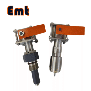
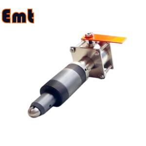
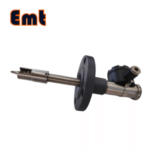
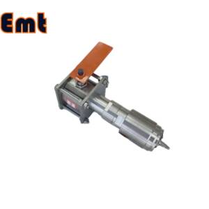
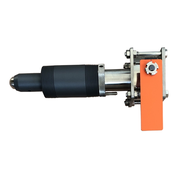
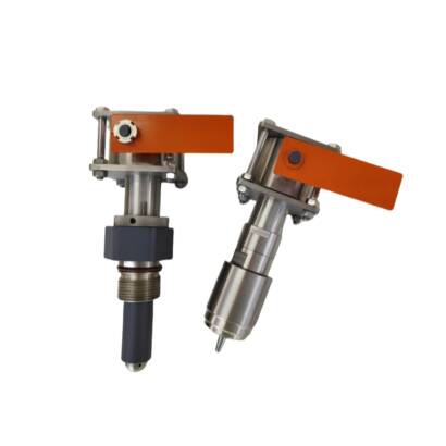
It is an intrusive, bidirectional trigger pig signaler used to monitor the passage of the pigging device. When the pigging device passes through, the bidirectional triggers inserted into the pipe trigger the actions of their respective displays:
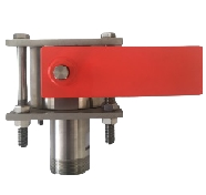
B: The indication flag changes from a horizontal position to an upright position;
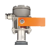
C: When the indicator flag changes from a horizontal position to an upright position, the SPDT electrical switch operates and remains in place.
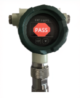
D: The digital time display starts timing and stores the actual time when triggered. After the SPDT electrical switch operates and maintains the timing set at the factory, the display returns to the standby state.
Working Principle
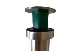
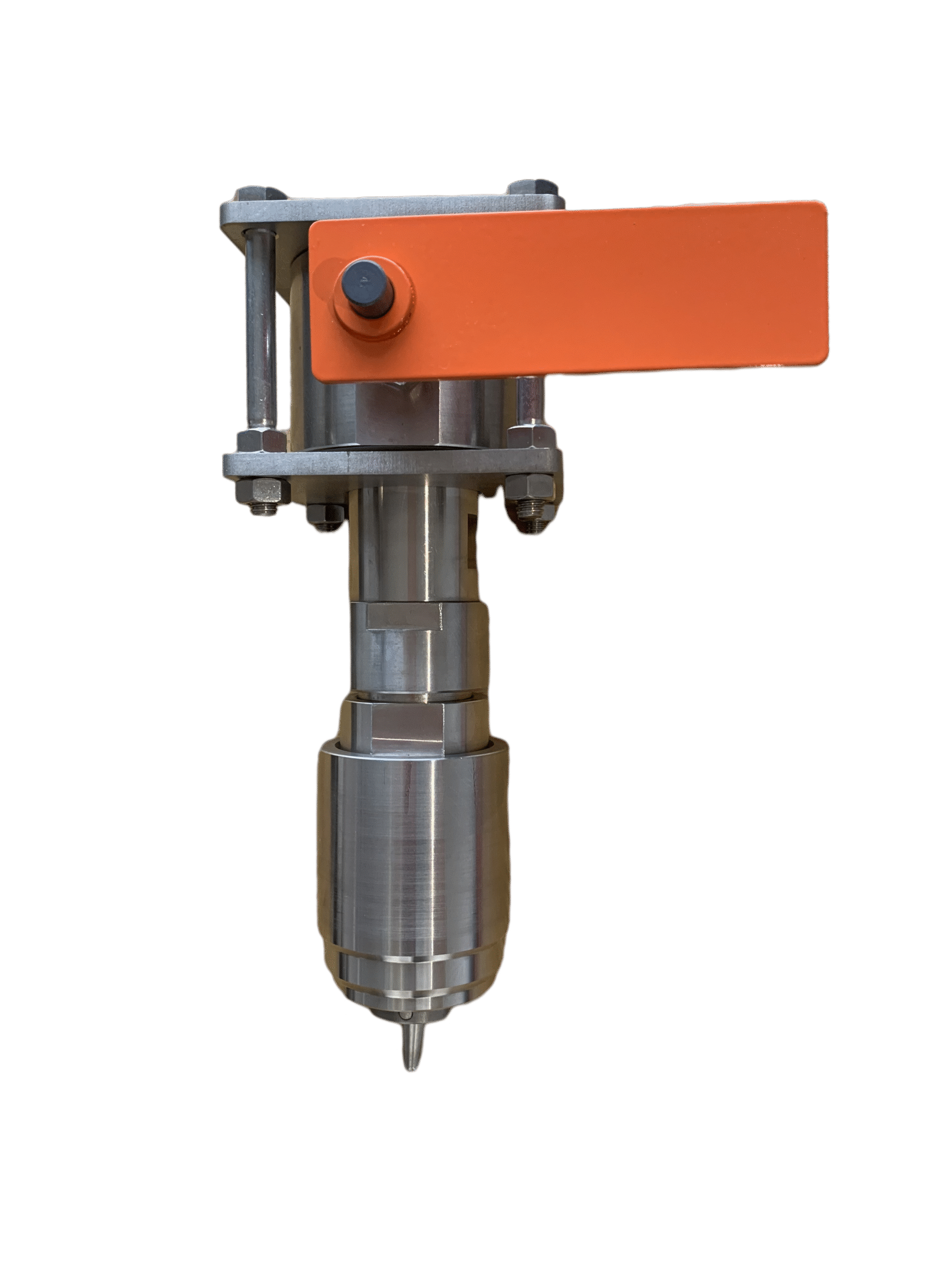
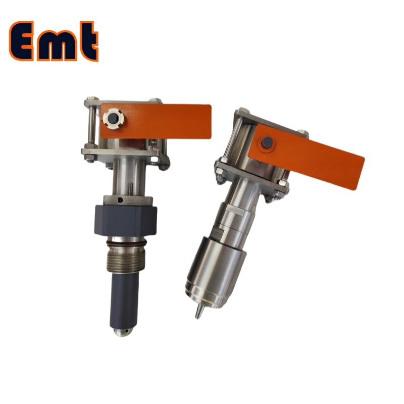
Take SN2-TQZ-BBXXX as an example. The end of the plug assembly installed on the base has a bidirectional triggering pin, which is inserted into the pipe near the pipe wall. When the pipe cleaning pig passes, the pin is toggled, pulling the connecting rod to make the flag pop up. After the flag pops up, it remains in the repelling pop-up state before manual reset, indicating that the pipe cleaning pig has passed.
After the pipe cleaning pig passes, the pin will automatically return to its position. At this time, forcibly pressing the flag can reset it and enter the standby state.
If the flag fails to reset after pressing it, it means that the pipe cleaning pig is here and the pin has not returned to its position.
Pig Signaler Features
SN2-TQZ-BBXXX is intrinsically explosion-proof (not an electrical appliance, so it is not an “intrinsically safe explosion-proof appliance”)
The pig signaler has no electrical parts and no friction or collision between metals.
The penetration depth of the ball indicator striker is designed to be adjustable, with an adjustment range of 0~±10mm.
Main Parameters of the Pig Signaler
Working pressure: 0~5MPa, 0~16MPa, 0~26MPa (or designed according to user requirements)
Ambient temperature: -20~150℃ (comprehensive value, may vary for specific media)
Base material: ASTM A105N, ASTM A350 LF2, AISI 316L (or designed according to user requirements)
Installation Method
Drill a hole above the pipe at the installation location according to the instrument model and pipe wall thickness.
Hole size: Pipe hole size ≥φ51mm.
Adjust the extension length of the striker by rotating the plug assembly according to the pipe wall thickness so that after installation, the front end of the plug assembly is tangent to the inner wall of the pipe.
Secondly, complete the welding and installation process in four steps.
a) Insert the ball indicator with the adjusted extension length into the pipe opening, rotate the plug assembly so that the straight line formed by the flat mouth of the plug assembly is parallel to the direction of the pipe. Weld a point at the weld to position it. When the step on the base cannot complete the self-positioning of the insertion depth, manual positioning is required during welding.
b) Unscrew the plug assembly from the base and place it in a clean packaging box.
c) Weld the base firmly to the pipe.
d) After the base cools down, apply lubricating oil on the sealing surface of the plug and the base and install the plug assembly back to the base. The straight line formed by the flat mouth is parallel to the direction of the pipe. Then, adjust the installation accuracy by following the steps below.
Installation and Inspection
According to the pipe wall thickness, rotate the plug assembly to adjust the extension length of the striker. Therefore after installation, the front end of the plug assembly is tangent to the inner wall of the pipe.
Secondly, complete the welding and installation process in four steps.
a) Insert the ball indicator with the adjusted extension length into the pipe opening, rotate the plug assembly so that the straight line formed by the flat mouth of the plug assembly is parallel to the direction of the pipe. Weld a point at the weld to position it. When the step on the base cannot complete the insertion depth positioning itself, manual positioning is required during welding.
b) Unscrew the plug assembly from the base and place it in a clean packaging box.
c) Weld the base firmly to the pipe.
d) After the base cools down, apply lubricating oil to the sealing surface of the plug and the base and install the plug assembly back to the base. The straight line formed by the flat mouth is parallel to the direction of the pipe. Then, adjust the installation accuracy through the following steps.
Adjust the Installation Accuracy
Check the installation accuracy by measuring the external dimensions (taking L=153 plug as an example):
Measure the actual distance Standoff from the top surface of the base to the outer wall of the pipe and the wall thickness WTH.
lass=”yoast-text-mark” />>According to the formula A=153-(Standoff+WTH)-26, calculate the distance A from the second end face of the plug to the upper end face of the base, and screw the plug assembly to the corresponding position.
The two planes on the sleeve should be parallel to the direction of the fluid in the pipeline. If not parallel, rotate the plug assembly counterclockwise to adjust it to parallel.
Tighten the locking nut to prevent the plug assembly from rotating.
Direction Adjustment for Type B and Type C Monitors
After completing the installation steps, if you want to adjust the direction of the monitor, you need to slightly loosen the four nuts under the monitor flange. Then you should rotate the head clockwise, and tighten the four loosened nuts after reaching the appropriate position.
Maintenance of Pig Signaler
When leakage occurs on the base of the pig signaler , it indicates that the seal of the device is damaged and needs to be disassembled and replaced. The seals visible on the outside can be replaced on the spot, and other internal seals are recommended to be returned to the manufacturer for replacement.